Saturday, August 30, 2014

IPTV and Multicast: Video Hub Office (VHO)

My dear friends of transmission fraternity,


How are all of you? I hope all of you enjoyed Ganesh Chaturthi with lots of fun. I am very sure that the time ahead will bring lots of happiness and prosperity to all of your lives. Let us begin with where we had left before in our topic that related with IPTV and Multicast. Today we are going to talk about another component in the IPTV delivery system and that is the Video Hub Office or VHO. Let us recall the IPTV delivery model for our reference before we begin to study on the VHO. The Reference diagram of the IPTV deliver as was mentioned in the Blog before is there on the figure and we are going to actually see the VHO part that is in the intermediate location. We study now about the various parts of the VHO and how a VHO system is constituted.


1. Dimensional Positioning of the VHO:

As discussed in the previous BLOG a SHO is a place where you have major feeds of National Content and feeds of other channels coming in and aggregating. The SHO actually consists of a lot of encoders and transcoders that are converting the RF output of the signal to a provided multicast IP channel and is then transmitting this to the network. A VHO is actually a regional hub or a regional distribution system of this architecture. So as to say typically in a City there may be one VHO. If there is a large IPTV network rollout then the SHO will be one or two in the country for a Service provider. Say this can be in a location like Mumbai or Delhi or anywhere, close to the feeds. VHOs are typically in the regions like Bangalore may have one VHO. Many small cities will have one VHO and so on. The concept of VHO is similar to that of a Relay Center that used to be there in the DoorDarshan days.

2. Work of VHO:

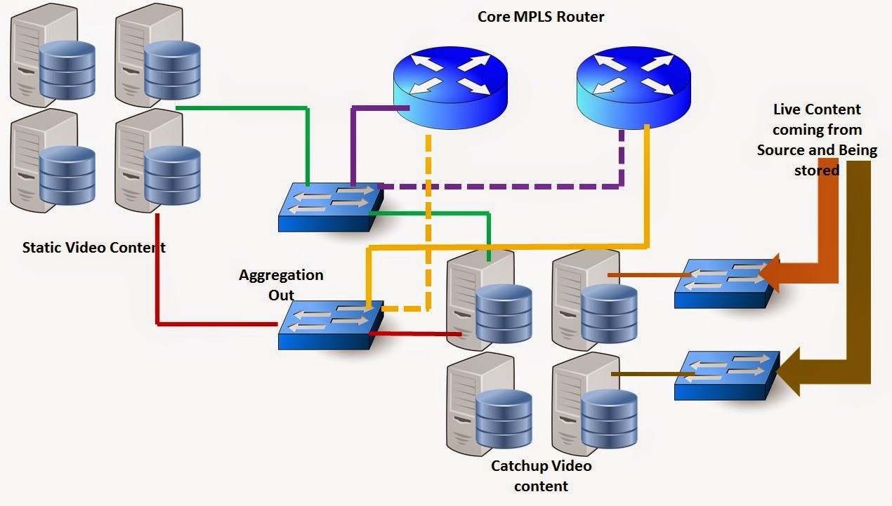
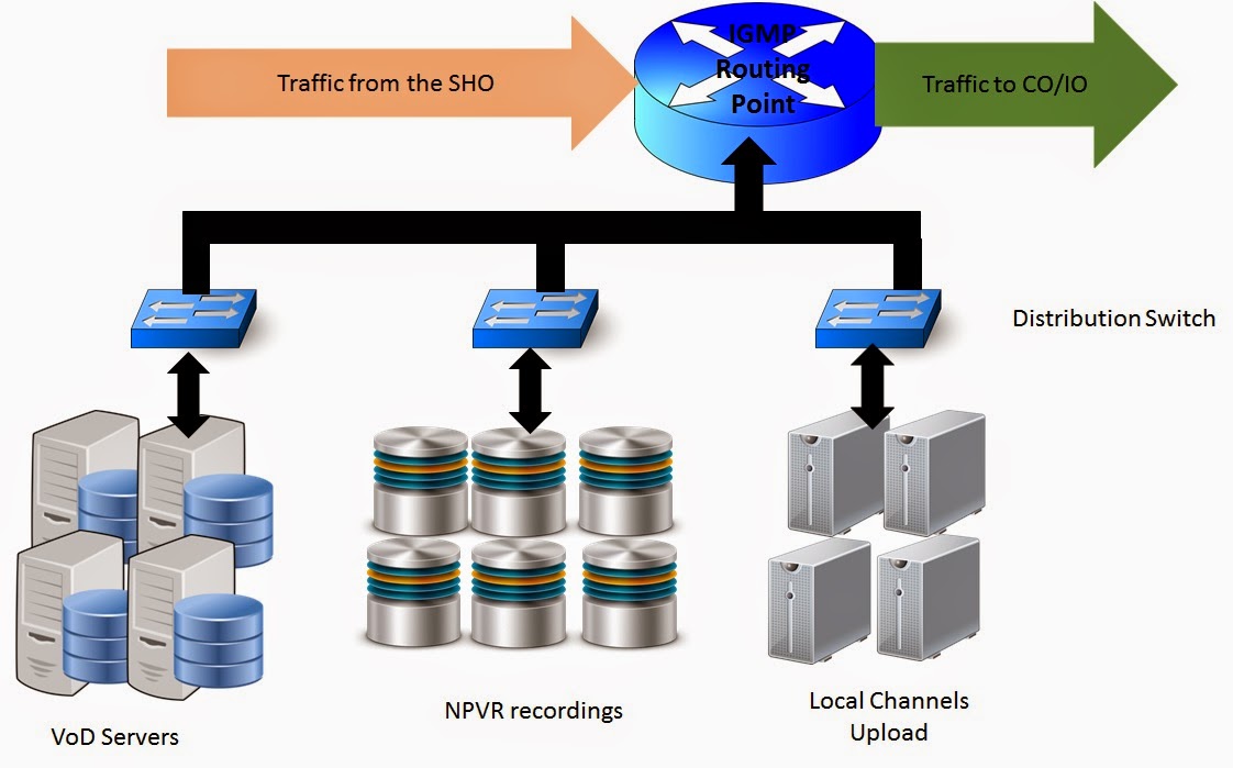
The first and foremost work of a VHO is to efficiently distribute the traffic towards the customers, which are IO (Inter-mediate Offices) and CO (Cable Operators). VHO is actually acting as a intermediate route point for all the traffic. In order to understand more part of the work that the VHO does we need to actually see a high level diagram of the VHO unit. This diagram is a very basic diagram of the VHO, of course there are several other components and this goes well with the SHO also. Let us see the diagram over here.

Basic High Level Structure of the VHO
As we can see that apart from only relaying the traffic that is being received from the SHO the VHO also has components related to VoD (Video on Demand), NPVR (Network Private Video Recorder) and Local channels. Let us dissect all these components one by one in this section.

2.1 VoD (Video on Demand):

IPTV has a very good option of Movie watching that can be taken on Demand. This means your movie at your time, with of course a kind of payment that you have to make in this entire thing. The set-top box of a normal IPTV service has a kind of a storage which is encrypted and the movie is downloaded over there for a particular time-frame for which the user makes the payment. Of course, more the time of storage that you would want more would be the charges. The VoD servers actually have a lot of movie content that may be regional and uploaded to the servers. There may also be a lot of popular movie content that may be kept at a local storage in the VoD servers. It is logical to think that the download would be much more effective if the content is placed near. In most of the cases the central content of VoD that may be in the SHO and based on the popularity in the region this may be actually downloaded to the local servers of the VHO. There can be a kind of popularity logic based on the demand of the content that may be actually served to the users. 

It has to be understood that every content over here has a definite UNICAST IP and the transmission of a VoD content happens over a UNICAST BW. So let us understand now the QoS part. Suppose many users are actually downloading the VoD content to their Set Top Boxes so that there is a congestion in the network, what happens to the live transmission of the Multicast. Answer is very simple the Multicast is always kept at a higher priority, with a higher DSCP marking in the system. This is done to avoid even the slightest disturbance in Live TV services due to congestion in the VoD. 

2.1.1: Optimizing the VoD delivery:

It can be now understood that if VoD is sacrificed at the cost of Multicast then what would actually be the value of such a service. Well, not to worry. Remember we talked about Multicast and then conditional multicast. As we can see that the router of the VHO is actually IGMP enabled and responds to the join and leave requests that actually come from the CO. Hence at every time not all the channels are transported to all the COs and there is BW free. This free BW and the reserve BW for VoD is used in case of a high demand of the content from VoD from seperate users.  

But then what happens if the same content is demanded at more than one CO locations. In such a case the following can be done. The UNICAST VoD can be sent as a conditional Multicast to the COs using IGMP v3 (This is very seldom done) and the VoD stream can be given in a drop and continue fashion and BW can be optimized in a real way. 

In the case of congestion in the VoD stream there can also be TCP window sizing that actually increases and decreases the window size as the resource availability is there and thus keeps the channel alive for the transport. This may delay the transfer of the file but keeps it reliable. 

2.2 NPVR (Network Private Video Recorder):

NPVR can also be deployed in the CO layer for a better optimization but the practice is also to deploy it on the VHO. NPVR is a kind of a recording unit for the user that is in the VHO where there is an allocated space for him and then this content can be accessed as per his wish. NPVR enables the process of live recording and storage on the cloud. NPVR content can also be accessed by other users if there is a process of sharing possible. Let us take an example for this. Suppose you are watching a television series which you like very much and you keep it recorded, or you actually set a kind of time to record the television series at a particular time and store it in the NPVR of the IPTV cloud and then access it at your convenience. Also if there is a sharing enabled in your NPVR partition then this can be actually watched by other users that you assign as friends when they actually want it from your location.  The storage can actually also be in your STB but then this does not enable the feature of sharing and multiple access of the content. A content that is stored in the NPVR can be accessed via the Television or actually by any other device. NPVR enables the multi-screening environment. 

2.3 Local Channels:

Every region has its own local content publishers as well. Some of these publishers restrict the viewing only to that region as their popularity index is huge. Many of them can also provide the feed to other providers who actually broadcast this nationally. For example, if we are in Kerala, there will be several channels in Kerala that actually  provide the local regional program and many of them are only local providers. These channels are actually hosted on the VHO of the IPTV Service provider. For these channels the Live feed and acquisition remains in the VHO station itself and then those are transmitted towards the customer. 


So my dear friends, this is a high level view of the VHO. We will explore more in the SHO and the VHO areas as we go ahead. SHO and VHO both are really a full sea of equipments in the IPTV deployment, so there needs to be a lot of study don on the same. Only high level study is not enough. 

Till then, 

Take Care.....

Cheers.....

Kalyan

Wednesday, August 27, 2014

3G and 4G are not about Video only........

Hi Friends, 

When we talk about the technologies like 3G and 4G the first thing that comes in to our minds, especially in India, is the way we would be able to watch videos online. While, online video watching definitely is one of the key factors of 3G and 4G, however this is not the only aspect and for which there needs to be a deep introspection of what kinds of services can actually be expected to improve in the 3G and 4G Scenario. The marketing of these technologies often speak about the "No Buffering" experience, which is good enough, however is that the only thing that 3G and 4G propound of is questionable. 

Let us see some of the services that are actually not very focused in the 3G and 4G scene but can make a lot of difference.
File Sharing by P2P and HTTP
1. File Sharing: We have heard this a number of times and also used this but never actually weighed this in the context of 3G and 4G services. File Sharing, whether it be in the HTTP or in the P2P domain consumes a heavy amount of Bandwidth in the system and this for sure is one of the services that gets a serious boost in the 3G and 4G platforms. A mobility network that has 3G and 4G properties with appropriate amount of Caching in its own ISP core actually helps a lot to boost these services as they are very bandwidth hungry. Today with the age of online education and diverse content distribution, file sharing is a purpose that is definitely going to help the cause of 3G and 4G.
Cloud computing Flow

2. Cloud Computing : When we were small kids or probably in the 5th grade we saw the computer for the first time. Mobile phones were a fancy in the "Star Wars" movie and imagining things to be done on the mobile phone apart from talking was something like a madness. However today the realities have changed. Computer is no more an amalgamation of Processing unit, Input output unit and Storage unit in the same place bound together. Today even the notebook or "Laptop" as we call it is slowly becoming obsolete. Why so? Well Cloud computing. The OS, the storage the Infrastructure may not be at the same location at all. They may be all connected by a private or public network. The peripheral device may be a thin PC without a processor, a tablet or a Mobile Smart Phone. In some of the cases the media may be wired however in most of the cases the media is wireless. Network accessed from the Cellular region and in that case it is more and more necessary to have the network having the Bandwidth of 3G or 4G. A user may upload the files to a centralized cloud location and may try to retrieve it from anywhere anytime and in this case the network and its bandwidth is of a crucial factor. 
VPN services, wired and wireless

3. VPN Services: Today the major problem of the metro cities is the fact that there is an increasing demand for space in both the commercial and the Residential sector. Most of the offices, especially the smaller ones are actually planning to provide work from home facilities to the employees who are mostly doing a desk job in the office. In this case there is a need of a VPN that connects the employees to the office and all the employees work well in a home environment, contributing to the peace of the city, by not increasing traffic and also reducing pollution. On the other hand there are many employees who are field staff and are constantly on the move from one client location to another and these people are actually always connected to the Office network by means of a VPN. The difference of course is that these people connect by means of a cellular connection and if that connection is of a high BW like HSPA+ or LTE then the work becomes very easy. 
Peer to Peer transfer

4. Peer to Peer Service: While most of us would say that these services are actually on the decline, the statistics tell a different story. Peer to Peer services like Torrent and e-Donkey are actually on the rise due to the fact that most of the content, actually 80% are not present on any HTTP site. The only reason these are sometimes inhibited by ISPs is because of the consumption of BW that happens in these kinds of services. While one may debate that the P2P way is a very unorganized way of information interchange, the fact is, it has the access to maximum amount of content that actually may not be available on any web-server. This actually mandates the availability of a very good and robust network that the user has an access to.  The BW rates of HSPA+ and LTE actually allow the users even on the cellular network to be encouraged to use the P2P services. 
Database Services

5. Database Services: The big problem with Data is that it is too much in quantity and it is too unstructured at times and sometimes not accessible at the right time. To solve these problems there was the innovation of database systems. A normal evolution of these systems were to have a central location of storing and structuring the data and to make the relevant query results available to the users on thin clients located across the region and also the globe. As we already established the incumbency of cloud computing, the database services is more like that. The access to the database should be secured and should be of quality BW. In the event the user is a mobile user the BW rates of HSPA+ and LTE actually help this happen. 

6. Video/Audio Download: While the live streaming and progressive download mechanisms can be actually handled by the optimization techniques to an extent (Though this way of handling is becoming obsolete in age of quality), there is a lot of content in the video and the audio format that are actually downloadable. In this case there is a full download of the entire file from a particular web-server to the client location. In such a case the 3G and the 4G network should be able to suffice with smooth download with a greater TCP window size. Though the TCP window size variance is not only a factor of a fat pipe BW but also the proximity of the content (Which is why you need to place Content Caches in the system, nearer the proximity, bigger the window size, higher is the BW usage for download) a higher BW should always be available for usage. 
These are some of the many reasons why 3G and 4G are not only about video. I am not trying to propound a new theory over here, but actually trying to remind that these technology have a wider purpose and these purposes should also be explored. Looking at these technologies to be only a kind of video boosters is the same like buying a microwave oven with loads of feature only for heating food. 
So let us be judicious and rational. 
Cheers,
Kalyan
Image Courtesy: www.google.co.in 

Monday, August 25, 2014

IPTV network architecture intro and the SHO (Super Hub Office)

"If somebody could stop technology we would have still been in the stone ages. Technology and Innovation cannot be stopped by apprehensions or bureaucracy. "

- After listening to so many Apprehensions

My dear friends of transmission fraternity, 

I hope all of you had a very nice weekend and here I am to release another post that is based on Multicast. In the last post we got a fair amount of Idea of Conditional multicast and how it actually works in the network. IGMP v2 and IGMP v3 were also explained through a RFC link. As we go higher up the technology implementation there would be some amount of deviation that will happen from the transmission. Evolving in Telecom is actually to go up the layers of the OSI model. As a Telecom engineer we are actually expected to reach at least to Layer-4 from the classical Layer-1 or now even Layer-0. 

1. How an IPTV network looks like

The difference between normal TV and an IPTV is actually the "interactive" nature of the TV services. IPTV actually helps the user to interact with the TV provider so as to have supreme experience of Television viewing. The user can change camera angles, see a summary of all the channels by PIP, see polls and popularity, take an active part in TRP generation, watch video on demand for many channels and so on. 

Typically an IPTV network looks like the following architecture as shown below. 

Block Diagram of an IPTV network generally deployed
 As we can see in the figure the IPTV network is a layer of many MPLS networks that are doing Multicast and Unicast transmission. It is not necessary that all the networks may be owned by a single operator. Different parts of network may be owned by different operators and the revenue can be shared on the basis of signals and distribution only. Due to the CAS regulations it is apparent that all the channels are made visible or available at all the parts of the network to actually reach the users. Each and every object shown as the cuboid have different function and different revenue model in the IPTV systems. 

2. SHO/SHE:

SHO stands for Super Hub Office and SHE stands for Super Head End. Most of the times they are co-located at one place. However, there may be cases where the SHE is the point where only the Feed is taken from National Channels and then there may be multiple SHO that actually take the input from the SHE. The content that is taken in the SHO are generally as follows. 
 > National TV Channels (channels that are applicable all across the country/ Region)
 > Universal video content for VoD (Video on Demand). 
 > Any content from other source when can be transcoded to a TV channel. 

2.1 Live TV Acquisition:
The diagram below shows the typical architecture of a live TV acquisition System in the SHO

Figure Describing the Live TV acquisition system and final ingestion to the network

As we can see in the figure the live TV channels are fed by means of the dish array that is there in the SHO/SHE. The dish Array feeds the system to a Encoder which actually provides an IP to these channels. The encoder defines a channel by a particular multicast IP and that is from where the IP output starts to be ingested to the system. One Encoder may cater to one or more channels and there may be redundancies of encoders as well. 
The encoder out actually goes to an aggregate switch network that actually sends the respective encoder signals to an acquisition server. One Acquisition server has 2X1Gb/s NIC for in and the same for out. Depending on the total number of channels and the expected redundancies in the system there may be a number of Acquisition servers available in the network. 
To understand how much Bandwidth may be required per channel the dimensioning of the Acquisition servers may be done in that respect. Please keep in mind that some amount of margins should be kept in such cases for any data spike or untoward incidences. 

SD Channels - 3-5 Mbps
HD Channels - 8-15 Mbps
Audio Channels - 1Mbps

One NIC of the Acquisition server is that of 1Gb/s so based on that there can be a distribution of the channels across the servers and also there can be a planned m:n redundancies. 

The output of the Acquisition servers are finally aggregated on a Switch that provides a 10Gb/s or nX10Gb/s output to the Core MPLS router. The redundancies are also understood clearly. From here the signals are entering the network and sent via the multicast IP network.

As told in the article before, at this state there is no need for conditional multicast as most of the content is sent via plain multicast to the system. 

2.1 The VoD (Video on Demand) System in the SHO:

There may be a kind of argument that the VoD is more often localized to the VHO, however, the SHO also has servers of VoD that have video content that are catering to a viewing of the entire Country or Region. The SHO maintains a proper storage of the video content that can be watched over the video in the storage servers. This actually helps to ease out the load in the VHO, where the content that is popular every where may not be maintained individually. 

The VoD distribution in the SHO may contain static video as well as the video that may be sourced from the live TV channels and that may be watched later. This sourcing may be operator influenced or user influenced. Mostly user influenced storage is not done in the SHO level it is more importantly done in the VHO level, which we will understand in the next post. 

The schematic of the VoD flow in the SHO is provided below. 

Video on Demand in the SHO

As we can see that there is static content in the VoD system flow as well as Live content. Each of the video content may have a specific IP that may be actually available as a separate stream in the EPG. Mind it, that the VoD traffic flow unlike the live TV is Unicast. Needless to say there will be more BW consumption if most of the VoD content is always there in the VHO locally stored that becomes popular. There can be also an implementation of a dynamic object cache in that respect, which understands the full logic of popularity vs the demand of the content in the VoD system flow. 

A part of the system is also made up of Catchup storage content that the user may want to store now and see later. Catchup storage in the SHO is generally operator influenced rather than it being user influenced. There may also be a kind of a link from the catchup storage to go to the static storage. Each of this content can also be watched as per the broadcast message and user request from each VHO. 

3. Summary Block Diagram of the SHO:

So to summarize the SHO or the Super Hub office can have a block diagram as shown below. 

Generic Block Diagram of the SHO
As you can see clearly that the sections we covered the Live TV acquisition and the VoD segment is there in the system. However, what is interesting is that apart fro mthe Live channel delivery there is also a kind of interface to the OTT (Over the Top).

While video is already been watched in the form of Live TV and VoD for the managed customers (Customers who are subscribed to the services) of the IPTV operator, the video or the content is also in the form of unmanaged content in the Internet, so that the same content can be watched, provided a proper App is available to watch it,  over a Tablet, mobile or many such devices. OTT or over the Top content actually helps the customers to have an access on Live streaming, catchup video and video content in a PAID or a FREE option as decided by the operator. 

The OTT mode of transport provides an additional aspect of the revenue for the operator for the content. This revenue may come in the form of advertisements or Pay per view from the user. 

We will study more on the OTT aspect as we go forward. 

There is a lot....lot.....lot more to be explored in the field of multicast and Television. While most of us, network guys, working with tier-1 operators are conversant on the Mobility transport and some ways the Fixed line Data transport as well, this particular field of IPTV transmission is really interesting to know about. Multicast delivery and IPTV is the future growth aspect of telecom also in India and this has to be understood very clearly. Although, I also am also not an expert, I am trying to aggregate and place in this platform most of which I know. I am confident that in the future, you will be able to explore more articles on the same and may have even more knowledge on the same aspect. Needless to say, I would also request each and every one of you to share your knowledge also in this interactive forum. Also share the blog post with your friends, acquaintances and rivals.

Till then, bye, take care. 

Cheers. 

Kalyan


Monday, August 18, 2014

CATV distribution and Conditional Multicast

"Looking through the glass always does not help building vision, vision is built when one actually steps out of the door to the open land and experiences it with all the senses that he/she possesses."

Aristotle

My Dear Friends of Transmission Fraternity, 

How are all of you? I hope you have read the last article on Multicast data transmission that I had put forward. The matter that I am going to present in this post is actually a continuation of the same.

1. Recap on the Multicast Traffic:


A multicast traffic is a stream of Data that has a destination address which actually when entering a switching device floods all the ports with the same stream except the port from where it is injected.
The behavior of the traffic is same as broadcast as per the flow is concerned however there are somethings that are different in the multicast traffic.
Multicast traffic can actually be grouped by means of IGMP and can actually be controlled by user based policy as compared to a broadcast traffic that can only be restricted by the means of BSC (Broadcast Storm Control).
Multicast transmission actually exploits the idea of the flooding state of the switch to its advantage and thus optimizes resources in the network to envision a drop and continue architecture of the traffic delivery. This is how more an more traffic can be pumped to more and more locations.
The Network reservation of the resources does not depend on the number of users but actually depends on the number of channels/streams that are do be delivered in the multicast delivery model.

2. Optimizing more resources on the Multicast delivery scheme:


Previously we saw the very basic of the transmission of Multicast traffic in the system, however this kind of plain multicast traffic is very good when it comes to the upper distribution layer. In a normal CATV delivery system there is a upper distribution layer and then there is a lower distribution layer or can also be called as the access layer. Generally the upper distribution layer is full of resources and there is not much of conditional access that is deployed over there. It is however the lower distribution layer that is devoid of the BW and where a conditional multicast can do wonders in the delivery scheme.

Let us see the actual model of the Multicast delivery scheme in a CATV network in ideal scenarios.

Distribution in a CATV network system
As we can see that a CATV entity is not just one entity. A CATV, the person who is actually your cable operator is not the person who is owning the content of the channel. So there will be a particular content owner who is having the access of the channels. This will be a big company. They have a master location from where the content is fed into their main router and this starts a multicast drop and continue across all the locations.

So then there is a content owner, which is actually the owner of the channels then there is this upper layer Distribution, who is called as the content distributor. Big Distribution companies, ISPs or Managed CDNs actually to this at their layer. Then there are SUB-Operators or Local Cable Operators (LCOs) who actually have their own infrastructure in certain areas of the city to feed to their subscribers directly. The LCO model can also have a SUB-LCO entity that actually owns one single point of distribution to the customer, but such kind of deployments and arrangements are really less in number.

2.1 Distribution done by the Content Distributor:


As explained before the content distributor does a plain multicast delivery as the probability of repeat-ability in that layer is very bleak. In that layer all the sub-operator would actually demand an access to all the channel feed at the same time in order to distribute to their subscribers from their end whenever required. In this case the availability of all the channels should be there in the Upper distribution Network all the time. So this is a kind of an unconditional plain multicast that is there in the network with drop and continue arrangement.  The picture remains the same as shown below.

Drop and Continue Distribution and Upper Distribution Layer
As we can see in the picture clearly that there is a proper load sharing of the drop and continue architecture that is present in the upper distribution layer. This ensures proper flow of traffic to all the points with least processing load on the routing entities.
Assuming there are about 200 Channels in the system and each channel has on an average BW of 5 Mb/s this is a total infrastructure of 1Gb/s that is provisioned. There can be more BW provisioned if there are more number of channels. to be very precise how the BW engineering can be done in the Upper distribution layer will be explained later as it will have considerations for SD, HD, 4K and Audio channels.

2.2 Distribution done at the Local Cable Operator Layer:


While the distributor may have the luxury of having a 1G or a 10G BW provisioning to provide all the channels in a plain multicast fashion in the system, same may not be the case for the access network provider or the local cable operator. The local cable operator has the feed of the entire channel in his DSLAM box from which he multicast the content to the access. However, there is a difference over here. The part that is played by the local cable operator in this case is a bit advanced as he does a kind of Conditional Multicast in the system. The Local cable operator uses IGMP to actually do the distribution.
To have theoritical details about IGMP please read the following links

IGMP Wikipedia Link
IGMP V2 (RFC 2236)
IGMP V3 (RFC 3376)

2.2.1 Traffic in the Head end:


The head end of the LCO acts as the IGMP Root of the system and takes in all the channels from the distribution layer of the distributor. Let us see the figure for this.

The Local Cable Operator Distribution topology
As we can see the local cable operator distribution topology actually takes in all the channel feed from the Upper layer distribution, however it does not feed in all the channels at the same time to the access network. 

2.2.2 Repeatability/Probability factor and conditional distribution:


The local cable operator is working in a particular region of the city and so there is quite a possibility that all channels may not be in demand at the same time in the network. Let us take the example of a particular region in the afternoon. At this time the demand may be only of the channels that are showing movie and some news channels. 

Let us say that across this region that we have depicted in our diagram there is a request for CNN, HBO and FTV Only from two regions. 

Users requesting from channel as they are pressing the Channel button

As we can see over here that the users have requested the channels and these requests go from the leaf DSLAM to the Root DSLAM  as channel requests. The Root DSLAM will register the fact that the request has only come for CNN, HBO and FTV in the network and so will only populate the network resources with these three Channels.

Thus effectively the network will not take the entire load of all the channels but will only take the load of 3 channels that have been requested by the network so the load decreases to 15Mb/s from a mammoth 1Gb/s.

The Root also takes care of the fact that from which side or which direction of the network the requests are coming so as to provide the Feed only to that direction. In this case the bottom leaf is not demanding any content and so there is no need to populate the bottom legs with the content. However, there are demands of three channels from left and two from the right. So the Root ensures to send the stream in a way that 15Mb/s flow towards the left part of the ring and 10 Mb/s flow at the right side of the ring. This further optimizes the Bandwidth.

Let us have a look at the picture below for a clear understanding.

On the Left there is consumption of 15Mb/s and on the right there is consumption of 10Mb/s

As and when new request from new channels will come more resources will be filled.

2.2.3 New Leaf Demanding the same Channel:


In our case above the leaf a the bottom was not demanding any channel. However, let us understand that what happens if the user now in the bottom leaf turns on the Set Top Box and starts demanding for a content that is already flowing in the system. Say in this case the user is demanding HBO content that is already flowing in the system. In this case it is seen that the HBO content is already been sent to the left side leaf and so the bottom leaf immediately gets the content from the left side leaf.

New Leaf demanding the content that is already flowing the system
Now, seeing this there may be a very interesting question that what if the leaf would have demanded a content that is available from both the ends, say FTV. Well, in that case the thing that comes into play is the link cost. A link cost is a complex function of Link BW, quality and available resources. The lowest link cost will actually bear the traffic in that case. Of course when there is a failure there will be a different scenario.

Also there may be another question over here in all of your minds. There is a content say Fox news that is being only demanded by the bottom Leaf and that is being served by the Root, now the left side leaf one of the user requests for Fox news then what happens? Will the stream be sourced back from the botoom leaf? The answer is no. The stream when it is already flowing to the bottom leaf , if,  is making a transit from the left DSLAM , then the stream is just made to drop on the left DSLAM and continue to the bottom leaf. However if the path of the stream to the bottom leaf is from the right then depending on the link cost the stream can be sourced from the bottom to the left or directly from the root.

2.3 How does the Cable operator benefit from this? 


Due to this mechanism of the conditional distribution using IGMP there is a heavy optimization that the cable operator does on the network resources that it owns. In this case he may not need to provision a full 1Gb/s bandwidth or he may provision but use the same bandwidth also to provide Internet connectivity and voice. This is called as the triple play which will see in later posts. Assuming that he does provide Broad band also on the same resource then a separate engineering need not be done on providing the TV and the broadband. He can easily put the broadband on the same infrastructure albeit on a lower CoS than the TV. So when there is less space occupied by the TV then there will be more BW to play with in the broadband. Also in the same link infra there can be a Video on Demand service.

The main idea is that as and when people watch the same channels over the same access network more and more BW is optimized for better distribution and thus OPEX decreases considerably. So say, for instance, when a match is on most of the people would be hooked to the match and there will be more resource savings and thus providing better quality of the system and more efficiency in the broadband.


So friends, from this we understand that Conditional Multicast in the access network with IGMP (V2/V3) is very much beneficial for the optimization of the whole network. Especially in the cable operator sector where there is very less infrastructure to play with, this comes as a boon in which the operator can graduate to a small scale ISP. 

We will cover more and more details on this thing called as Multicast. This is very interesting. 

Till then Bye and Take care, 

Cheers,

Kalyan

Friday, August 1, 2014

Video Multicast Systems (Introduction) and Drop and Continue logic

"The word Telecom, is no more related to Conversations, it is related to expressions, declarations, user-experience and emotions"

From my Recent Sojourns

My dear friends of the Transmission Fraternity, 

Hello! How are you? Yes, Long time!!!! But better late than never. In the past few months I almost had a kind of writers' block but then it feels really good to come out of that state and being able to lay down to you many things that I experienced in the past few months. Of course all of it cannot be comprised in one post but then there will be many of them I assure you. 

There are times in the life of an engineer that he would want to rediscover himself, he feels stagnated and wants to enter new domains, learn new things, satisfy his technical hunger and for that very reason I had taken a kind of sabbatical from the world of technical blogging, because it felt that I had only the same things to write without much variety. 

Today I bring to you one very important part or rather a section of recent telecom trends and that is a video multicast system.  

1. Multicast Traffic:
To understand this clearly we need to first get a clarity on what exactly is multicast and what is actually not. whenever the communication is done in both the ways with equal priority in both directions and equal adherence this is called as a unicast. Most of the telephone conversations, Internet sessions, P2P are an example of Unicast kind of system. In the communications field almost 95% of the cases are that of Unicast, because then and only then there can be the very important "Communication", but as I said in the first statement the trends in Telecom are changing and today Multicast is a reality. 

Let us in a very simple way understand how a multicast traffic flows. 

General Process of Multicast traffic Flow

As you can see that there is one location which has most of the content that needs to be sent and this is actually sent to a group of users that are actually wanting to view the content. Something like watching television or hearing to radio or things like that. However, one may have a very elementary question and that is "If this is what is Multicast, then what is Broadcast?" Well legitimate question and very nice too. Even I had the same doubt all over because the pattern of traffic flow in Broadcast is also the very same. 

However there are certain minute differences that a Broadcast traffic has with a Multicast traffic and these are. 

1. Broadcast is unconditional to a subnet whereas Multicast can be made conditional.
2. Multicast can be requested whereas Broadcast is not requested it is just received. 
3. There can be grouping of destination and source addresses in the case of Multicast but not Broadcast. 
4. Multicast can be restricted at a user plane, but broadcast no. 

All these four characteristics we will see in four different posts that is going to follow so that there is no overdose of study in our regular life that in itself is so busy. 

Let us now delve into some of the main uses of Multicast. 

1. IPTV
2. Any one to Many service. 
3. Multipoint Storage. 

2. Video Transmission of 200 Channels:
Of all the many uses of multicast the best use is that in the case of Video. Video transmission through multicast is one of the best ways of handling the heavy nature of traffic that video has. Imagine you are having around 200 channels and each channel of around 5Mb/s each minimum, if we were do to a unicast transmission then this will have to be like 1gbps per user. the same amount of reservation would also have to be done in the access/aggregate network. However, this is not at all commercially feasible, because if this were done then Television services would cost you a bomb, even more than a business class flight ticket from Mumbai to Los Angeles. 

So what do we do in this case. To understand this let us follow the figure below. 

4 main clauses of Video Multicast

Looking at the clauses above it is apparent that the content is huge but then it is repetitive per user. So there needs to be a kind of a mechanism where the same content is delivered every where and the content is actually sent to a location then replicated over there. 

2.1.Drop and Continue Model
This replication of data is a primary thing in Multicast that gives it an edge in high bandwidth services delivery like Live video. 

To understand more let us see the figure below. 

Drop and Continue Transmission Architecture of Multicast

The figure above is in real sense called as the drop and continue model in the filed of multicast transmission. The Bandwidth of the ring is determined by not the number of users but actually the amount of total content that has to be transmitted. So 200 channels of 5 Mb/s each makes the Bandwidth equal to 1000 Mb/s or 1Gb/s. So the operator has to make a 1Gb/s ring in the system irrespective of how much is the number of users. The topology can also be MESH or whatever based on the number of fall-back paths that the operator desires. 

In this case the operator is actually user volume independent and the bandwidth of the topology/infrastructure remains constant despite use in the number of viewers. 

2.2 Drop and Continue Logic:

Multicast addresses are always of the type 01:00:XX:XX:XX:XX in the MAC sublayer and in the Layer-3 they are all having the Class D IP addresses that are actually more or less reserved for Multicast. So each and every channel has a Multicast IP address that is sent to the user. In the case of Multicast there is no Mac learning so in the Layer-2 the traffic is always in flooding mode without any restriction. 

Keep this in mind that had this traffic been a Broadcast traffic there would be the restriction of a Broadcast Storm Control (BSC) which is not the case in the event of a Multicast traffic. Hence seeing the Multicast category of the Mac address the BSC does not kick in and traffic is flooded to all the ports in the same VLAN. 

As you can see in the drop and continue port the traffic ones it comes in then the traffic is sent to the access and also replicated along the infrastructure. 

So my friends Drop and continue is not a magic, it is actually exploiting the most important faulty state of a switch and that is the flooding state. To exploit flooding property of a switching device in a controlled way leads to an efficient transmission of multicast traffic. 

Till then take care of yourself and always remember whenever you plan with science it is the best, but science only comes in the purest forms when you decide to shun your ego. 

Cheers, 

Kalyan


Sunday, May 4, 2014

Check your stress level friends; Life is not a reversible event.....

" A Profession is only meant to satisfy your technical and financial hunger, making an obsession out of a profession is not desirable."
                                                                                          Recent events......

My dear friends of the transmission fraternity,

After a long hiatus due to some occupational reasons I take this opportunity to write a post again in my blog. I wanted today to actually discuss about the emerging trends in video transmission and its future but my thoughts and inputs were disturbed by some very uncalled for news.

Friends, why is it like this that sometimes committed telecom executives who are there for the cause are really not rewarded and not actually understood in their better span of the career? Why is it so that some people who have actually laid their hands in developing and maintaining a fault free network are not actually very concerned about their lives when it comes to health and fitness?

Readers of my blog, I would want to actually stress one point over here and make this very straight, "Machines are for men however men are not for machines...." Please do not let the machines take a toll and controll over your life.

Yesterday night I heard three such sad news where transmission experts of the age of 30 - 35 have fallen prey to heart and brain stroke and have had to bid a final adieu to this world at a very tender and productive age. Sad, very sad, however let us understand before coming to any advisory conclusions as to why such a thing actually happens?

We may be advised a lot about taking care of our health but let us face it the stress levels in the field of telecom is immense and the pressures of the Indian telecom scenario is huge. Over and above that the Indian Telecom Industry gives very few options for a person to have a parallel growth path. After visiting countries of the west such as US and Europe and understanding their organisation structure I have come to a conclusion that dramatic changes are required in the working model of an Indian Telecom Firm.

In India the process of quantifying experience is archaic and obsolete. Experience primarily means a person with high amount of work-ex, eventhough he/she might be sitting on a stone. So primarily a person who is working for say 15 years and has a big brand in his resume will be given a higher preference than a person who is say 5 years old but has got good knowledge base. This understanding leads to frustration, and killing of ideas that a fresh mind can actually contribute towards the development of newer technologies and newer ways of revenue generation in the organization.

I am not saying seniority should not be respected but there should be a parallel path of growth. Not every person can be a manager and not every person can be an expert technically so there should be two parallel ladders of growth as it is there in the west.

This frustration often leads to higher stress levels at ages of 30-35 where a person is infact in the last leg of  proving his excellence but is not allowed to sometimes. Stress leads to such diseases.

Heart stroke, brain stroke, burn-out, inappropriate metabolism, messed up lifestyle are some of the very common disorders. The person is so obsessed with work that he doesn't actually understand the risk to his health and also messes up his family life.

My advice to my friends, who are facing these is go a bit slow. There is no fun in risking your life or health in something that is only carrying a material value for a small bit of time. If something untoward happens then it is you and your family who will suffer. The industry will and must go on at its pace.

Please, please my friends do not stretch too much. If a network goes down for some moments it is not leading to mass destruction, it is only a distruption of service, which can be fixed by patient and logical troubleshooting. Not that do not be committed but also be health concious. If you are at an age and in a position where night events are taking a toll on you, stop it. Talk to your seniors, if they understand then well and good and if they do not look out for options... It is not the end of the world. After all your knowledge and commitment are your assets only till the time you are healthy and living.

My sincere condolences to the family members of Mr Vivek Pillai and Mr Sanjay Gohel. I happened to meet Vivek once in a technical discussion, have not had the opportunity to meet Sanjay. May the almighty give the strength to their families to bear this loss and always be with them. I am sad and bereaved that telecom world has lost such young an potential talents.

This is a tremendous loss.

We as a fraternity, are always behind their families.

Amen.

Kalyan Mukherjee