THE MAIN ISSUE FROM TRANSFORMING FROM A CLASSICAL TDM NETWORK TO A MORE COMPREHENSIVE NEXT GENERATION NETWORK THAT HAS A HOMOGENEOUS MIXTURE OF TDM, PACKET AND OPTICS IS THE INABILITY TO MODIFY AND MOULD ONE'S PERCEPTION....


From my recent experiences (Some bad... Some good...Some "horrible")
My dear friends of the Transmission Fraternity,
Good Day to all of you and wish you a very happy weekend ahead. In India, this is the time of Ganesh Puja and like any other colorful festival this is of a very high importance to the social and religious fabric of India. But... wait a minute...... how does Lord Ganesha figure out in our field of Telecom???? Confused? Well not so.
Today let us understand the logic of celebrating Ganesh Festival and its significance to Telecom. Planning and provisioning in Telecommunications is much about taking the right decision in the most economical manner to optimize the network, so that the delivery and then the sale of the service is more and more on the profitable side of the business than just an obligation of delivering it. This is just like how Lord Ganesha, by his intelligent ways of solving problem salvages any situation without resulting to much of overheads and conflicts.
A person who is actually designing the network in such an aspect so that it can generate long term revenue without investment of much of physical resource, should be a planner, a more scientific one, however one who is only doing it for the heck of delivering the service, is more of an implementer or simply a "Copy & Paste" person. If the network is not bringing profitable revenue, then for sure the planning of network has been wrong. More quickly it brings profitable revenue, more efficient has been the planning. Just like Lord Ganeshas ways, a planning engineer should be the revenue optimizer and reliever of technical pains that an organization may foresee to deliver a service.
Let us take an example for understanding this:
There is a network of Wi-Fi and Mobility where there are 5 access nodes in the access rings with one NodeB each and one Wi-Fi access point each. The peak BW of a Node B is say 28Mb/s and that of the Wi-Fi is around 44 Mb/s. There needs to be an access network planned for the aggregation of this 5 nodes. How to do it?
There may be several ways of implementing this aspect and there may be several ways to deliver the services. Let us see the conventional (less profitable) and the non -conventional (More - profitable) way of delivering this.
CONVENTIONAL WAY:
The conventional way is the pure transmission way where every BW is important, whether it is being used or not.
So the following calculation is used.
5 Node Bs of 28 Mb/s = 5x28 = 140Mb/s
5 APN of 44 Mb/s = 5x44 = 220 Mb/s
Total = 140 + 220 Mb/s = 360 Mb/s
Conventional Planner of a good nature :
On a SDH back-haul network this would be taken to be a full 360 Mb/s of Provisioning which would mean a full ring of 360 Mb/s = 8XVC-3s or even 3XVC-4s. Hence a ring of 8XVC-3 is established in the entire system of EoSDH with or without MPLS and then the following logical network is realized.
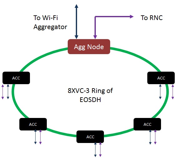
As seen in this picture each and every access node has a drop one of Wi-Fi and one of the NodeB. The total Bandwidth expended in the ring is actually 400Mb/s or 8XVC-3. This is more than the sum of the entire peak Bw of all the sites.
So the planner here is assuming the following and this is the mistake.
> In this access ring there will be always peak traffic from all the NodeBs and all the Wireless APNs all the time.
> There will not be any kind of treatment of traffic to which should be high priority and which should be low priority.
> Both the services should get the dedicated BW, whether they are using or they are not using in the transport infrastructure.
However, there are some good things that the planner has done which can actually classify him to be a better data planner and having potential.
> Planner has used less number of WAN ports.
> Planner has used more instancing and is actually instancing the service in different SVLANs or different instances to avoid any kind of cross talk.
> There is proper isolation between two Node Bs and two APNs of Wifi in the network.
> There is proper isolation of Node B and APN in the same access node also.
I am still assuming that the planner has done this, and if yes, at-least the basics of data planning is clear to the planner.
NON CONVENTIONAL WAY:
The non conventional way actually is more data-centric than more transport centric. Let us understand one thing to understand the non conventional way of planning. We had BTS and we had the BSC. So each BTS had around 2 E-1s to 4 E-1s each. This would mean that each BTS is having a capacity to run around 120Voice channels at the same time. With some amount of compression this can accommodate 400 users also simultaneously. So if an area is having more number of subscribers did we increase the carriers. The answer was no.
A thumb-rule calculation was the fact that for every 1000 subscribers you can actually spend an E-1. This factor was even higher in the case of mobility as there were good amount of compression and a probability of mobile subscriber leaving a site and joining another was very high.
The only thing was that, this calculation was done by the engineers at the switching centres who are having an idea of the traffic quantum in a cell site and thus used to give the figures to the transmission.
This was when you are considering a 2G kind of deployment. However, when the deployment phase goes to more of packet based access (Where the last mile device is Ethernet Handoff) then this flexibility of BW allocation is not to the MSC or the RNC but it is more to the transport. This is because the handoff is now not a fixed multiple of 2Mb/s but a combined port of 100Mb/s or 1Gb/s.
Not all sites will transmit the peak BW at the same time (Concurrence):
The non-conventional planner actually understands this philosophy of concurrence and tries to reach to a rational BW in the access ring. The planner uses this concurrence phenomenon to actually reach to a conclusive BW and thus ensures that there is full guarantee of the High available services and there is good amount of availability of low class services.
Thus the planner initially does a good amount of ratio and normalizes it to the nearest VC-4 or VC-3.
In this case the planner sees that the total peak BW of the entire service is 360Mb/s however the amount of traffic will never be of that level.
Contention and Prioritization (What is important and what is share-able)
Out of this 360Mb/s the signalling and synch traffic (Mandatory and always flowing) accounts to 20Mb/s in the entire ring (2 Mbps per site NodeB or APN). The rest are good amount of prioritized traffic.
In the 3G there is a voice per Node B of around 4 Mb/s so that gives another 20Mb/s of committed traffic.
So 20 + 20 = 40Mb/s of this traffic is totally committed and have to be provided in the line irrespective of anything else.
The rest 320Mb/s is data and out of which some are priority data and some are non - priority data (Best Effort).
the figure below explains the entire BW profiling.
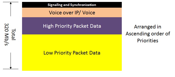
This is the figure that the user is deriving for the entire BW distribution. A high end packet service will contain many streams of data some of which are real time and some of which are non real time. The non real time are the ones that may not be susceptible to congestion as there is re-transmission, only thing that is affected in such cases is the throughput. Hence these services are given the maximum over-subscription. In this figure the Yellow portion is actually attributed to the Non - Real Time data. Maximum over-subscription is done to this portion only.
Let us see in the figure below how the BW is attributed and contented in the network.

So due to this now the BW is provided in the following manner.
20Mb/s + 20Mb/s + 160*0.5 + 160*0.1
= 20 + 20 + 80 + 16
= 136 Mb/s
= 1XVC-4 or 3XVC-3
By this process a total saving of Back-haul of 5XVC-3 is done which is equal to 250Mb/s. So the planner is effectively saving 250Mb/s of physical resources and delivering a good service of around 360Mb/s in it. As the number of site increases the user can rationally increase the resources.
So the final figure is.

Now in this case when the Voice is of low usage the BW is apportioned to the Packet data.
There is good prioritization.
There is of- course good instancing.
In short... The planner is not only thinking about service delivery but also thinking about Profitable service delivery. Definitely due to low usage of back-haul BW there will be less usage of Physical resources and thus increasing the longevity of the network elements and milking more money from it.
Such planners like to make the company profitable and want to always have more RPU with less investment.
ARCHAIC AND OLD SCHOOL PLANNERS:
While we discussed about good planners and very good planners, who try to benefit the network and some of them actually make the network as good profit engines by increasing the longevity, there are some who actually are physical resource guzzlers, and do not have any care of the amount of physical resource usage. They are just planning the network for the heck of service delivery and have no interest in network profitability. They are a pain to the sales personals in the operator industry as they totally reduce the profitability of the network and thus bring no substantial earnings from the service delivery. They are happy just making the traffic through and getting the ping from one side to another. The sales persons of such operators should pray to Lord Ganesha regularly, as each and every order marks in the overall reduction of profitability in the organization.
Understanding the case above the old school of planning will actually realize the network in the following manner.
From each access site they would pull two EoSDH trails, one for the NodeB traffic and one for the Wi-Fi APN.
Resulting into a Logical Topology ( Only the Good planners would understand the word Logical topology though) like this.

As shown in the figure above let us now calculate the number of VCs that are being used.
For one Node B 14VC-12 Main and 14 VC-12 for protection Leading to 28XVC-12 each site.So for 5 such node Bs this is 28X5 = 140 VC-12s = 280 Mb/s
For One Wi-Fi = 1XVC3 for main and 1XVC-3 for protection = 2XVC=3 = 100Mb/s. So for 5 Sites this is 5X 100Mb/s = 500 Mb/s
Total for all provisioning = 780 Mb/s ( WOOOOOW and they still think they will make profit!!!!)
Also let us now look at the number of ports.
At each access location 2 wan ports are used and in the aggregate 2 for each access this makes 10 WAN ports as opposed to only 2 in the case of Good planning.
So this means 10 Wan ports and as new access sites are added on the same ring this means more and more WAN ports on the aggregate.
So in some days the Aggregate module is kept underutilized but the ports are exhausted.
The planning is done in such a way as if the planner had some kind of an Animosity towards the rising profits of the organization and would like to cut it off by any chance.
Well this was an example of Efficient .... Very Efficient and Not at all Efficient way of deploying the same service.
I leave it upto you my friends as to what you want to become. I would also urge the Sales people in the operator industry to rethink and revisit the technical aspects of their network.
Telecom service provider is a business where the revenue (Top - Line) is an effort of the Sales people for sure but the Profit ( Bottom - Line) is dependent on how good the planners are in the conception and the implementation phase.
Remember making more trails doesn't give money, running traffic on it does.
May Lord Ganesha Bless us all on that note.
Cheers!!!!
Kalyan

.jpg)
.png)